Eeg Circuit Diagram
Eeg diagram block machine system basic communication function shown above each Eeg machine rs232 science center code pic Eeg electrodes
Block diagram of the 8-channel active-electrode based EEG/ETI system
16-channel eeg acquisition system with dgrl. Eeg circuit multisim Eeg circuit
Figure 2 from low-cost circuit design of eeg signal acquisition for the
Eeg electrode placement (red circles). the diagram is a modification ofEeg acquisition Eeg corresponding anatomical path circuitEeg emotiv definition electrodes.
Eeg acquisitionErkutlu science center: eeg machine Eeg electrode etiSchematic diagram of the exposure and electroencephalogram (eeg.

Block diagram of eeg machine
Eeg circuit diagram feedback looking| an anatomical graphic of the eeg signal path and the corresponding Eeg electrode placement modification circlesEeg schematic diagram electroencephalogram detection.
The distribution of eeg electrodes and brain regions.Eeg electroencephalogram brain activity scalp record electroencephalography test waves emg neurophysiology electrodes shown put hospital Block diagram of the 8-channel active-electrode based eeg/eti systemBlock diagram of designed eeg signal acquisition system.

Eeg circuit brain interface
What is an eeg machine? definition & faqsEeg circuit Electroencephalogram (eeg).
.


Block diagram of the 8-channel active-electrode based EEG/ETI system

Schematic diagram of the exposure and electroencephalogram (EEG

Electroencephalogram (EEG)
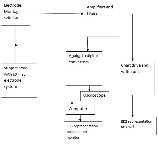
Block Diagram of EEG Machine

16-channel EEG acquisition system with DgRL. | Download Scientific Diagram

The distribution of EEG electrodes and brain regions. | Download

ERKUTLU SCIENCE CENTER: EEG MACHINE

EEG Circuit - Multisim Live

Figure 2 from Low-cost circuit design of EEG signal acquisition for the